
Subnet Chart:Internet Protocol (IPv4)
This is an Internet Protocol (IPv4) Subnet Chart. You can use this to quickly look up how you might need to subnet your network. At the bottom there is a quick how-to on calculating subnets.
For more information on subnetting, see RFC 1817 and RFC 1812.
Class address ranges:
Class A = 1.0.0.0 to 126.0.0.0
Class B = 128.0.0.0 to 191.255.0.0
Class C = 192.0.1.0 to 223.255.255.0
Reserved address ranges for private (non-routed) use (see RFC 1918):
10.0.0.0 -> 10.255.255.255
172.16.0.0 -> 172.31.255.255
192.168.0.0 -> 192.168.255.255
Other reserved addresses:
127.0.0.0 is reserved for loopback and IPC on the local host
224.0.0.0 -> 239.255.255.255 is reserved for multicast addresses
Chart notes:
Number of Subnets - "( )" Refers to the number of effective subnets, since the use of subnet numbers of all 0s or all 1s is highly frowned upon and RFC non-compliant.
Number of Hosts - Refers to the number of effective hosts, excluding the network and broadcast address.
Class A
| Network Bits | Subnet Mask | Number of Subnets | Number of Hosts |
| /8 | 255.0.0.0 | 0 | 16777214 |
| /9 | 255.128.0.0 | 2 (0) | 8388606 |
| /10 | 255.192.0.0 | 4 (2) | 4194302 |
| /11 | 255.224.0.0 | 8 (6) | 2097150 |
| /12 | 255.240.0.0 | 16 (14) | 1048574 |
| /13 | 255.248.0.0 | 32 (30) | 524286 |
| /14 | 255.252.0.0 | 64 (62) | 262142 |
| /15 | 255.254.0.0 | 128 (126) | 131070 |
| /16 | 255.255.0.0 | 256 (254) | 65534 |
| /17 | 255.255.128.0 | 512 (510) | 32766 |
| /18 | 255.255.192.0 | 1024 (1022) | 16382 |
| /19 | 255.255.224.0 | 2048 (2046) | 8190 |
| /20 | 255.255.240.0 | 4096 (4094) | 4094 |
| /21 | 255.255.248.0 | 8192 (8190) | 2046 |
| /22 | 255.255.252.0 | 16384 (16382) | 1022 |
| /23 | 255.255.254.0 | 32768 (32766) | 510 |
| /24 | 255.255.255.0 | 65536 (65534) | 254 |
| /25 | 255.255.255.128 | 131072 (131070) | 126 |
| /26 | 255.255.255.192 | 262144 (262142) | 62 |
| /27 | 255.255.255.224 | 524288 (524286) | 30 |
| /28 | 255.255.255.240 | 1048576 (1048574) | 14 |
| /29 | 255.255.255.248 | 2097152 (2097150) | 6 |
| /30 | 255.255.255.252 | 4194304 (4194302) | 2 |
Class B
Network Bits | Subnet Mask | Number of Subnets | Number of Hosts |
| /16 | 255.255.0.0 | 0 | 65534 |
| /17 | 255.255.128.0 | 2 (0) | 32766 |
| /18 | 255.255.192.0 | 4 (2) | 16382 |
| /19 | 255.255.224.0 | 8 (6) | 8190 |
| /20 | 255.255.240.0 | 16 (14) | 4094 |
| /21 | 255.255.248.0 | 32 (30) | 2046 |
| /22 | 255.255.252.0 | 64 (62) | 1022 |
| /23 | 255.255.254.0 | 128 (126) | 510 |
| /24 | 255.255.255.0 | 256 (254) | 254 |
| /25 | 255.255.255.128 | 512 (510) | 126 |
| /26 | 255.255.255.192 | 1024 (1022) | 62 |
| /27 | 255.255.255.224 | 2048 (2046) | 30 |
| /28 | 255.255.255.240 | 4096 (4094) | 14 |
| /29 | 255.255.255.248 | 8192 (8190) | 6 |
| /30 | 255.255.255.252 | 16384 (16382) | 2 |
Class C
Network Bits | Subnet Mask | Number of Subnets | Number of Hosts |
| /24 | 255.255.255.0 | 0 | 254 |
| /25 | 255.255.255.128 | 2 (0) | 126 |
| /26 | 255.255.255.192 | 4 (2) | 62 |
| /27 | 255.255.255.224 | 8 (6) | 30 |
| /28 | 255.255.255.240 | 16 (14) | 14 |
| /29 | 255.255.255.248 | 32 (30) | 6 |
| /30 | 255.255.255.252 | 64 (62) | 2 |
Supernetting (CIDR) Chart
CIDR - Classless Inter-Domain Routing.
Note: The Number of Class C networks must be contiguous.
For example, 192.169.1.0/22 represents the following block of addresses:
192.169.1.0, 192.169.2.0, 192.169.3.0 and 192.169.4.0.
Class C
| CIDR Block | Supernet Mask | Number of Class C Addresses | Number of Hosts |
| /14 | 255.252.0.0 | 1024 | 262144 |
| /15 | 255.254.0.0 | 512 | 131072 |
| /16 | 255.255.0.0 | 256 | 65536 |
| /17 | 255.255.128.0 | 128 | 32768 |
| /18 | 255.255.192.0 | 64 | 16384 |
| /19 | 255.255.224.0 | 32 | 8192 |
| /20 | 255.255.240.0 | 16 | 4096 |
| /21 | 255.255.248.0 | 8 | 2048 |
| /22 | 255.255.252.0 | 4 | 1024 |
| /23 | 255.255.254.0 | 2 | 512 |
The first thing you must know is that the common number system used world wide is the decimal system (otherwise known as base 10). What makes the decimal system a base 10 system is that it is based on grouping numbers by 10's. It is believed that the system evolved because we have ten fingers and ten toes which over the years we have used for counting. I use mine all the time (grin). We name the ten digits: zero, one, two, three, four, five, six, seven, eight and nine.
The decimal system has a 1's place, a 10's place, a 100's place, a 1000's place and so on. We say the number places are grouped by 10's because multiplying each number place by 10 gives you the next number place. So: 1x10=10 (the 10's place), 10x10=100 (the 100's place), 100x10=1000 (the 1000's place) etc.
Let's look at the decimal number 103 by place.
103 <- read from right to left
We have a 3 in the 1's place
We have a 0in the 10's place
We have a 1 in the 100's place
Thus: 100+0+3=103
By now you probably feel like you have attended Kindergarten for the second time in your life? Sorry about that but it is very important that you understand the concept of what a number system is, and what it is based on before we look at binary.
[Understanding binary - base 2]
Binary is a base 2 system, and thus groups numbers by 2's and not by 10's like the decimal system. We name the two digits: zero and one. The binary system has a 1's place, a 2's place, a 4's place, an 8's place, a 16's place and so on. We say the number places are grouped by 2's because multiplying each number place by 2 gives you the next number place. So: 1x2=2 (the 2's place), 2x2=4 (the 4's place), 4x2=8 (the 8's place), 8x2=16 (the 16's place) etc.
Let's look at the decimal number Let's look at the decimal number 103 in binary format:
01100111 <- read from right to left
We have a 1 in the 1's place
We have a 1 in the 2's place
We have a 1 in the 4's place
We have a 0 in the 8's place
We have a 0 in the 16's place
We have a 1 in the 32's place
We have a 1 in the 64's place
We have a 0 in the 128's place
Thus: 0+64+32+0+0+4+2+1=103
Okay, Let's test your skills. Here is a list of binary numbers, try converting them to decimal and check your answers at the end of this post.
10000000
11000000
11100000
01000000
10000011
10010001
11111111
If you were able to convert these numbers to decimal then congratulations! You're ready to move on to the next section.
[Understanding a subnet mask]
Now that you understand what binary is, let's have a look at our two subnet masks from the beginning of my post:
192.168.1.0 / 255.255.255.0
192.168.1.0/24
The concept of a subnet mask is simple. You have a network and you have hosts on the network (anything with an IP address is a host). The subnet mask determines what portion of the TCP/IP address represents your network and what portion can be used for your hosts. Because I am a simple person, I think of it like this; The network number represents the street I live on, and the host portion is used for the numbers on all the houses on my street.
A subnet mask of 255.255.255.0 means that the first three octets of the address will be used for the network, and thus our network number is 192.168.1. This means we can have 254 computers on this network, because the fourth octet is not being used by the network portion of the address. We know this because of the 0 in the subnet mask (255.255.255.0).
We call each of the number sections an octet because we think of them in binary, and there are eight possible bits in each section. Eight bits is an octet. 11111111 in binary is 255 in decimal (did you do the conversions?). So our decimal subnet mask 255.255.255.0 displayed in binary is going to be:
11111111.11111111.11111111.00000000
If you count all the ones, you will find that there are 24 of them. Now look at the subnet mask examples again.
192.168.1.0/255.255.255.0
192.168.1.0/24
Do you see why both subnet masks are the same? The number 24 is the number of bits used in the network portion of the address, and is short-hand for writing the address/subnet mask combination. It becomes important to understand this when you start dividing your network into multiple sub networks.
[Understanding Subnetting]
Before reading this section, you should have a good understanding of what a subnet mask is and how binary bits represent the subnet mask.
Simply put, subnetting is dividing your network into multiple sub networks. To go back to my silly example about houses and streets, subnetting gives you multiple streets in your neighborhood.
There are two methods for dividing your network into multiple sub networks; One is to simply change your network numbers keeping the same subnet mask. The other is to subnet your network into smaller sub networks.
Keeping the same mask:
Your network could be divided into two or more networks by changing the network portion of the address such as 192.168.1 and 192.168.2 and keeping the same subnet mask.
Example:
192.168.1.0/255.255.255.0
192.168.2.0/255.255.255.0
Doing this would give you two separate networks with 254 hosts per network. This is a very common method of dealing with multiple networks. However, back in the good old days you had to pay for every IP address you used, and if you had 25 computers on your network you probably would not want to pay for 254 addresses! The answer to the problem is...subnetting.
Subnetting a network:
Subnetting is when you use bits from the host portion of your address as part of your network number. This let's you subdivide your network at the cost of host addresses, which is great if you're paying for every host IP address. It will save you money because you pay for fewer TCP/IP addresses. Confused? Here is where understanding binary is important.
Lets look at a new subnet mask:
255.255.255.224
As you can see in the fourth octet, some of the host portion of this subnet mask is now being used for part of the network address. Which means we are now using some of the binary bits in the fourth octet for our network numbers, and that gives us fewer hosts than our old mask (which gave us 254), but gives us more networks (which is why we call it subnetting).
How can we tell how many networks and hosts per network this new subnet mask will give us? Well... we shall have to use some of our newly acquired binary skills.
The first task is to find out how many bits in the fourth octet are being used? The decimal number is 224, what is the decimal number 224 as represented in binary?
The decimal number 224 in binary is:
11100000
We have a 0 in the 1's place
We have a 0 in the 2's place
We have a 0 in the 4's place
We have a 0 in the 8's place
We have a 0 in the 16's place
We have a 1 in the 32's place
We have a 1 in the 64's place
We have a 1 in the 128's place
Thus: 128+64+32+0+0+0+0+0=224
So our complete subnet mask in binary is:
1111111.11111111.11111111.11100000
We now know that three bits from the fourth octet are used. How can we tell how many sub networks we're going to have? This requires some math- sorry. The formula is: 2n-2, where n is the number of bits being used from the host portion of our subnet mask.
Note: We subtract 2 from the total because you do not count all 0's or all 1's.
The formula for three bits is:
23-2=6
In simpler terms:
(2x2x2)-2=6
So our network is sub divided into 6 networks. Next, we want to know what the network numbers are, and how many hosts we can have on each of the 6 networks?
What is the first subnet? Let's have a look at the bits in our fourth octet again. The bit that gives us the answer is the (1) closest to the first zero, and in this case it is the 3rd bit from the left.
11100000
The 3rd bit will start our first network, and the 3rd bit is in the 32's place (remember binary). Start adding the value 32 to itself six times to get the six network numbers.
Note: A quicker way to find our starting network number is to subtract our mask from 256.
256-224=32
Here are our network numbers:
32
64
96
128
160
192
A better way to display this is:
192.168.1.32
192.168.1.64
192.168.1.96
192.168.1.128
192.168.1.160
192.168.1.192
The host addresses will fall between the network numbers, so we will have 30 hosts per network. You're probably wondering why it's not 31? The answer is that the last address of each subnet is used as the broadcast address for that subnet.
Example:
Subnet:192.168.1.32 / 255.255.255.224
Address Range: 192.168.1.33 through 192.168.1.62 (30 hosts)
Subnet Broadcast Address:192.168.1.63
Quiz:
Let's test your skills- write the address range and broadcast address for the following subnet. You will find the answer at the end of this post.
Subnet: 192.168.1.128 / 255.255.255.224
Address Range?
Subnet Broadcast Address?
If we we're paying for our TCP/IP addresses, we would only pay for one network and host combination, thus paying for 30 hosts and not 254. It could mean some real savings, it also frees up the remaining addresses for other organizations to use.
Let's look at another subnet mask:
255.255.255.240
How many bits are used from the host portion? To find this out, we need to know how the decimal number 240 is represented in binary.
The answer is:
11110000
So four bits are taken from the host portion of our mask. We do the same math as before:
24-2=14
In simpler terms:
(2x2x2x2)-2=14
We will have 14 sub networks, and what will the network numbers be? Look at the fourth bit, it's in the 16's place:
11110000
Note: A quicker way to find our starting network number is to subtract the value of our mask from 256. So: 256-240=16
Start adding 16 to itself- fourteen times to get all 14 network numbers:
16
32
48
64
80
96
112
128
144
160
176
192
208
224
A better way to display our subnets is:
192.168.1.16
192.168.1.32
192.168.1.48
192.168.1.64
192.168.1.80
192.168.1.96
192.168.1.112
192.168.1.128
192.168.1.144
192.168.1.160
192.168.1.176
192.168.1.192
192.168.1.208
192.168.1.224
The host addresses fall between the network numbers. So we will have 14 host addresses on each of our 14 sub networks (remember: the last or 15th address is the broadcast address for that subnet).
If you had a small company with 10 hosts and needed to have a static IP address for all of your hosts, you would be assigned a network/subnet mask and a valid IP address range.
Here is an example of what that might look like:
Network: 205.112.10.16/.255.255.255.240
Address Range: 205.112.10.17 through 205.112.10.30
Subnet Broadcast Address: 205.112.10.31
[Answers to Binary Conversions]
10000000 = 128
11000000 = 192
11100000 = 224
01000000 = 64
10000011 = 131
10010001 = 145
11111111 = 255
[Answer to Subnet Question]
Subnet:192.168.1.128 / 255.255.255.224
Address Range: 192.168.1.129 through 192.168.1.158
Subnet Broadcast Address: 192.168.1.159
Configure A Router With Packet Tracer
Computer networking professionals getting started with Packet Tracer may find the interface to be flustered. Being a development program, this is only natural. However, learning how to configure a router with Packet Tracer will put professionals on the right track to mastering the program in about half an hour.
By this time, you should already have the Packet Tracer download and have it installed on your computer. Open the program and select the router from the lower left-hand corner, and drag it into the center of the sandbox screen as seen below. (Click for larger picture)

We will be setting up a very basic network that allows two computers to communicate, so the next step is to select end devices from the bottom left-hand corner and drag it to the sandbox screen. Do this twice to make two computers appear below the router.
Now select connections from the same bottom left-hand corner. When you connect like-devices(Such as a router and computer) you use a crossover cable, so you should select copper cross-over cable from the second menu to the immediate right. Click on Router0, and connect the cable via FastEthernet0/0 as seen below:


Configuring The Router In Packet Tracer
A router that is turned off doesn’t work very well! Click on your router to bring up the configuration menu and verify that it is turned on.When on, there will be a small green light below the switch as seen in the diagram.

Next we have to open the Ethernet ports to allow communication. Although they are physically connected, they are in a state that is known as being in administrative shut down. Now click on the CLI tab to access the configuration menu. If you’ve used the Cisco IOS before, you will notice it looks and acts the same way.
--------------------------------------------------------------------------------------------------------------
That’s it! You should now see a message similar to the following:
%LINK-5-CHANGED: Interface FastEthernet0/0, changed state to up
%LINEPROTO-5-UPDOWN: Line protocol on Interface FastEthernet0/0, changed state to up
Now we have to do the same thing for fastethernet0/1. If you don’t, there still won’t be a connection to PC1! Make sure to enter the IP address carefully as seen below:
---------------------------------------------------------------------------------------------------------------
1. Press Ctrl + Z to go back to the previous mode.
2. Type interface fastethernet0/1
3. Type ip address 192.168.20.1 255.255.255.0
4. Type no shutdown
---------------------------------------------------------------------------------------------------------------
At this point our router is configured properly. If you test out a ping, you will notice that the computers still don’t communicate, however!
Configuring The Gateway In Packet Tracer
Our last step is to configure the gateway on each desktop computer. The gateway is the address we assigned to the Ethernet port that the desktop is connected to. It will allow the computer to interface with another network, so our ping won’t work without it!
Click on PC0 to bring up the configuration menu. Under global settings you will find a field for the gateway. Enter the corresponding IP address of the router’s interface, which is 192.168.10.1. Then click the FastEthernet tab on the left column to set the actual computer’s IP address to be on the network. Use 192.168.10.2 for the IP address, and 255.255.255.0 for the subnet mask.

Do the same thing for PC1, only use 192.168.20.1 for the gateway address, 192.168.20.2 for the IP address, and 255.255.255.0 for the subnet mask. You can confirm that your network works by sending out a packet of information from PC0 to PC1, and vice versa. Click the packet icon on the right menu as seen below:

Click on PC0 and then click PC1. On the lower right of the screen you will see a message box that says “Successful.” If it doesn’t, you may have had a syntax error when putting in an IP address or router configuration command. Review your work or ask for help among the community if you are stuck.
Congratulations! You have a small working network. A real-world application of this very network would be to have two computers connected to the Internet, whereas the router would then be connected to your telecommunications company. (Or what we would call the “cloud”)
More advanced devices and topologies won’t be so easy, but you’re now on the right path to becoming qualified for the CCNA certification exam.
How the Transport Layer Works
The Transport layer- is the layer responsible for actually getting the data packets to a specific location. When we receive email, we want to open it with our email program- not anything else. So how does a computer know exactly where to route data to appropriate programs, all while dealing with multiple connections?
The Difference between TCP and UDP

How Do Transport Protocols Work?


Practical Uses of the Socket

The Anatomy of a TCP Segment
So now we know how data is routed, but what is the data made up of? As we learned in previous sections, we call the data at the Transport level of the TCP protocol a segment.
1. Source Port - A 16-bit field that specifies which port number the data segment originated from on the source machine.
2. Destination Port - A 16-bit field that specifies which port number the data segment is destined for on the receiving machine.
3. Sequence Number - A 32-bit field that specifies which sequence number the particular segment of information is assigned. The sequence number is used to number packets of information so that they may be counted on the receiving side- guaranteeing a successful and complete delivery of information.
4. Acknowledgment Number - A 32 bit field that specifies whether or not a segment was received correctly. The acknowledgment number is always one higher than the sequence number, since the receiving computer is expecting the next segment.
5. Data Offset – A 4-bit field that tells the receiving computer how long the header is, and where the data actually begins.
6. Reserved - A 6-bit field that is reserved for future use. Currently this field is represented as all zeroes. In the future, it may be likely that TCP will make use of this space for some reason or another.
7. URG - A 1-bit control flag that stands for urgent. If the value is 1, the information is urgent and should be dealt with accordingly.
8. ACK - A 1-bit control flag that, if set to 1, indicates that the Acknowledgment Number field is significant.
9. PSH - A 1-bit control flag that stands for push. If set to 1, all the information sent so far is sent to the receiving application.
10. RST - 1-bit control flag that stands for reset. If set to 1, the connection is reset.
11. SYN - A 1-bit control flag that stands for synchronize. If set to 1, then a sequence of numbers will be used to sort information packets. This also marks the beginning of a connection.
12. FIN - A 1-bit control flag that stands for finished. It also closes a connection, and indicates that there is no more data to be sent.
13. Window - A 16-bit field that is used for flow control. It indicates that a range of sequence numbers past the last acknowledged sequence number do not require further acknowledgment.
14. Checksum - A 16-bit field that checks segment integrity. A calculation is done on both the sending and receiving computer. This calculation is based on the segment’s information, so we can use it to check and see if the packet is indeed the same being received as it was sent.
15. Urgent Pointer - A 16-bit field that indicates the beginning of urgent information. Specifically, it points to a sequence number.
16. Options - A field that may be used to set various optional settings.
17. Padding - A spacer used to offset the Options field. Since every row must equal 32 bits, the Padding field must add to the Options field to equal 32 bits. Since the Options field may vary, variable Padding is needed.
18. Data - The actual data being sent to the recipient computer.
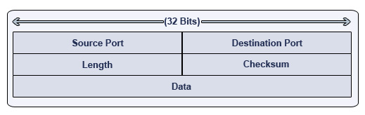
1. Source Port - An optional 16-bit field that specifies which port the datagram originated from.
2. Destination Port - A 16-bit field that specifies which port the datagram should be directed to on the receiving computer.
3. Length - A 16-bit field that specifies how long the UDP datagram is. This includes the UDP header and the data being sent. (The value is always at least 8, since the UDP header is eight octets.)
4. Checksum - A 16-bit field that operates much like the TCP counterpart. It is considered optional, however.
5. Data - The actual data being sent to the recipient computer.
You will notice that the datagram anatomy is much simpler- and that no source or destination information is included. So how does the data know where to go? As we briefly reviewed earlier, UDP uses what is known as a pseudo-header. This header will act as a guide for the datagram, and can determine whether the datagram was delivered to the right address or not.
Carrier Sense Multiple Access Collision Detect (CSMA/CD) Explained
Before we get into CSMA/CD in particular, we need to review who is vulnerable to collisions. Some types of data transmission are virtually invulnerable to collisions- while others are somewhat lacking in this defense.

CSMA/CD:Carrier Sense Multiple Access Collision Detect
First let’s take a look at what CS (carrier sense) is in CSMA/CD. Carrier sense is the ability of a network interface card (NIC) to check the network for any communication. Obviously if there is data being transmitted over the network, the NIC should not attempt to transmit data. If there is no traffic on the network, the NIC will then attempt to transmit the data. However, we can’t be sure that data isn’t in the process of being sent by other computers- so this is one possible beginning of a collision.


The Collision Detection and Solution Process
1 - A collision is detected.2 - Devices involved in the collision keep transmitting for a short period of time, to make sure all devices on the network see the collision (also referred to as the jamming signal)
3 – Each device sees the jamming signal, and invokes the back-off algorithm. Each device will have a random timer that determines when it can transmit again.
4 - When the back-off timer expires, devices are free to transmit data again. Devices involved in the collision earlier do not have priority to transmit data.
How to recover a PIX Firewall password
If you ever lose a password on a PIX Firewall and need to recover it, follow these steps:
if you ever need to recover a password on the PIX
here are the steps:
Requirements:
* You will need a console connection from the PIX to your machine
* You will need a TFTP server application running on your machine
(I personally use tftpd32, which can be downloaded for free
at http://tftpd32.jounin.net/)
1) Connect the console cable to your serial port and plug the RJ45 end
into the PIX port marked "Console". You can use Hyperterm (which comes
with Windows) or any other console program of your choice. I use
TeraTerm Pro, found at http://www.ayera.com/teraterm/.
2) Find out what version of software is running on your PIX. If you're
not sure, you can find out very easy in the following way. If you
are connected to the PIX via a console connection, simply reboot the
PIX and watch for the output. It will tell you which version is
running.
3) Download the corresponding helper binary file from Cisco, depending
on which software version is running on the PIX. For example, if you
were running version 6.3(x) you could use the file called np63.bin found
here: http://www.cisco.com/warp/public/11... If you were running
6.2 you could simply change the last characters on the above url to be
np62.bin. Download that file and save it to the root directory of your
TFTP application.
4) Next, reboot the PIX again and immediately after the reboot as it is
coming back up and displaying text in your console send a break sequence
with your keyboard. If you are using Hyperterminal with Windows the break
sequence is Ctrl-Break.
5) This will send the PIX into "Monitor" status and you will see the following
prompt on the PIX:
monitor>
6) Patch your computer into the inside or outside interface on the PIX via a
standard CAT 5 cable (i.e. patch from your computers NIC to one of the PIX's
interfaces).
7) Give your computer an IP address. For this example, let's use 10.0.0.1
with a gateway of 255.0.0.0
8) Start up your TFTP server program and keep it running.
9) Tell the PIX which interface you will be connecting to, as follows:
monitor> interface 1
*note interface 1 is inside, interface 0 is outside, but you remember that
from reading the ebook right? :)
10) Give the PIX a temporary IP address on the same network as your computer,
as follows:
monitor> address 10.0.0.2
11) Tell the PIX the IP address of the TFTP server (your computer)
monitor> server 10.0.0.1
12) Tell the PIX which file to copy:
monitor> file np63.bin
13) Start the TFTP copy
monitor> tftp
14) It should copy very quickly. If it does not you will get
an error message on the PIX and potentially on the TFTP server
software. If you do get an error, you likely have a cabling
issue or perhaps a typo of one of the above commmands.
15) Once the file is copied to the PIX, the PIX will ask if you are
sure you want to reset the password. Type "Y" for yes, and the PIX
will reboot.
16) After the reboot the PIX will now have a default telnet password
of "cisco" (no quotes) and no enable password.
That's about it. About 10 minutes of downtime and you and your PIX Firewall are back in action!
Add a second Router to your LAN
A brief guide on how to properly add a second (or third) router to an existing LAN that already has a
The general setup of SOHO Router's is similar. While some use a different subnet, every one I've worked with uses a Class C Private IP Addressing Scheme. I'm going to use the basic Class C private for this tutorial (192.168.0.0)
I'm going to give two setup guides:
The term “Router1” will refer to the router connected to the internet. Any others (ie: Router2, Router3) will be downstream of Router1
Version 1:
========
Router1 (LAN Side):
========
DHCP Enabled = Yes
Dynamic DNS = Anytime, Anywhere Network Access
Because ISPs don't assign static IP addresses, accessing devices your network remotely is tricky. One way around changing IP addresses is to use a Dynamic DNS service, which automatically tracks the changes to your network's public IP address.
You pobably use your broadband connections for all kinds of things when you're at home, but you can also take advantage of that connection to access devices on your network even while you're away. For example, you might want to view a Webcam, grab files off an FTP server, use a remote access utility like Windows' Remote Desktop, or even access the router itself to administer it from afar.
These sorts of things would normally be made possible by a router's port forwarding feature combined with knowing the public, or global, IP address assigned to your network by your ISP. The problem is that for most accounts, that public address isn't permanent and will change from time to time. It may not change very often — maybe every few days or perhaps even less frequently than that — but once it does, the address you've become accustomed to using won't work anymore. While you can always find the new IP address and begin using it instead, you can't look it up while away from home. Even if you could, the address will eventually change again.
Static or Dynamic
One way to eliminate this problem is to arrange for a static IP address through your ISP, but this isn't always feasible. For starters, getting one can cost $5 (or much more) a month. With some ISPs, a static IP option isn't available unless you upgrade to a more expensive business-class account (and that pricier service may not even offer any more bandwidth than you already have).
A better solution is to use a Dynamic DNS service that can automatically track the changes to your network's public IP address. These services let you set up your own specific DNS name and then will regularly update a database to make sure the name always points to your current IP address.
Configuring Dynamic DNS
The most common way to use Dynamic DNS is to configure your broadband router to automatically update the service each time it gets a new IP from your ISP. There are several Dynamic DNS services to choose from, most of which are free or available at a nominal cost. The two most popular are DynDNS and TZO. While both services are excellent, we'll focus on DynDNS here because it offers a free version and arguably has the most widespread router support. Almost every router offers some kind of Dynamic DNS support, but your router must support the particular service you want to use. You can access the Dynamic DNS heading in your router's admin interface to see which services it will work with (and you may be presented with additional options if you upgrade to the latest firmware).
Prior to making any router modifications, start here by creating a DynDNS. You'll need to confirm your account via e-mail before you can configure it — once you've done that, look for an Add Host link or go here.
In the hostname field, you can enter anything that means something to you, assuming it's hasn't already been used (let's say joesnetwork, for example). Then pick the domain name you want to use from the rather extensive pull-down list (there are 68 choices in all), make sure your IP address is filled in (it should have been done automatically), and click Add Host.
Now call up the Dynamic DNS configuration page of your router (the exact interface will vary depending on the make and model of your hardware). First ensure Dynamic DNS is enabled, specify the service provider you're using, and then enter your DynDNS user name, password, and the full host name plus domain name you choose (e.g. joesnetwork.dyndns.org). Be sure to apply the changes; a router reboot will probably be necessary.
Remember Port Forwarding and Internal Static Ips
Just as you would if accessing your network via an IP address, before you start using Dynamic DNS you should make sure your router's port-forwarding feature is configured appropriately so the router knows which IP address to forward incoming traffic to. For example, if you're setting up a Web server, forward port 80; an FTP server, port 21; or Remote Desktop, port 3389.
It's also critical that you assign a static internal IP address to any device you're trying to reach so that the router always forwards to the right place. Another way to accomplish this is to use the DHCP reservation feature found on many routers, which will make sure a given device always gets the same DHCP-assigned address.
Using Your New Domain Name
It may take up to an hour after you set up your DynDNS domain name before it's usable. Once active, all you need to do is use the domain name instead of the IP address with the relevant software. The nice thing about Dynamic DNS combined with port forwarding is that you can use the same name to access multiple systems on your network. As long as you've set up the port forwarding correctly, the type of software you use or port you specify will determine what you connect to.
Although the domain names that DynDNS offers aren't particularly memorable, they're probably sufficient as long as you're the only one that needs to know them. If you plan to allow others access to your network and want to use a more meaningful name, TZO offers a Dynamic DNS service that will let you choose a custom domain name for about $60 a year.
A final caveat: Be sure to check your ISP's terms of service before setting up a server that's going to be public and generate lots of traffic (especially a Web server), because some ISP rules prohibit customers from running such servers (particularly with consumer-grade accounts). It usually won't be an issue when you're setting up personal access, but in some cases ISPs may filter incoming traffic or terminate your account if it detects an unauthorized server. (Another of TZO's paid services provides a forwarding feature that will let you run a web server even if your ISP blocks port 80.)
There you have it. We've only scratched the surface of what Dynamic DNS can do, but the most important thing to remember is that it will ensure that your network is always locatable no matter how often your public IP address changes.
Batch file to test ip address range.
This is a cool batch script that I found to ping a range of IP addresses and report whether they respond to the ping.
Simply copy and paste this code into a notepad file and save with the bat extension (remember to enclose the save as file name in quotes so that it doesnt add a txt extension.

@echo off
SET t=0
:start
SET /a t=t+1
ping -n 1 -l 1 192.168.1.%t% > nul
if %errorlevel%==0 echo Host %t% is UP! >> 192.168.1.%t%-up.txt
if %errorlevel%==1 echo Host %t% is DOWN! >> 192.168.1.%t%-down.txt
IF %t%==999 Exit
Goto start
Network Tools - Rediscover batch file.
Today I'd like to share with you some light ideas about network troubleshooting in Windows XP.
Most of your network connection issues can be fixed with an very enigmatic command called “Repair”. You can find this by clicking right mouse button on network icon at System Tray area. Please take a look on a picture below.

Before my explanation I’d like to remind you an old technique to create a DOS batch file. A DOS batch file is a list of commands grouped in one file with extension “.bat”. Usually you execute in a single DOS command in a command prompt. If you have to do a few of them at once you must do that one by one. Instead of this you can create a simple text file where you list commands to do. After finishing just rename your file for i.e. mycommand.txt to my command.bat.
Let’s take a look how we can fix our networking problem with a small DOS batch file. Below you see a list of prompt line commands.
@echo off
arp -d *
nbtstat -R
ipconfig /flushdns
nbtstat -RR
ipconfig /registerdns
So, fill your repair.txt with these commands and close with .bat extension like this example:

For explanation what individual command stands for please read this followed Microsoft Technet Library example:
ARP - displays and modifies entries in the Address Resolution Protocol (ARP) cache. The "–d *" switch deletes all entries of IP addresses.
NBTSTAT - displays NetBIOS over TCP/IP (NetBT) protocol statistics, NetBIOS name tables for both the local computer and remote computers, and the NetBIOS name cache.
The “-R” switch purges the contents of the NetBIOS name cache and then reloads entries from the Lmhosts file and “-RR” switch releases and then refreshes NetBIOS names for the local computer that is registered with WINS servers.
IPCONFIG - displays all current TCP/IP network configuration values and refreshes Dynamic Host Configuration Protocol (DHCP) and Domain Name System (DNS) settings. The “/flushdns” switch flushes and resets the contents of the DNS client resolver cache.
I hope today tip will be useful for you.
Happy learning :)
Get Command Prompt On Remote System

For those of you who know the power of the command line, you also know that it is really useful to be able to run some of these command line tools remotely. There are a number of different ways to do this. I would like to share with you a couple of my favorites.
PsExec
If you are not familiar with PsExec, then this is going to be a bit of a revelation for you. PsExec is a freeware program that allows you to execute a command on a remote machine. If that command is a command line program, it will send the output of that command back to you.The real trick comes when you run the command console. Try this command:
psexec \\RemoteComputer cmd.exe
What this does is connect to the remote computer and then open a command prompt on the remote machine. You can then work with this new command prompt and it will execute all of your actions on the remote system!
In order for this to work for you, you need to have the admin$ share active on the remote computer (which it is by default) and you need to have account information with administrative access to the system. This is mainly used in situations where you have a Windows network and you are the administrator of the network.
SSH on Windows
If you have the time to set up something a bit more elaborate, I would recommend using SSH on your computer. If you set it up properly, you can have remote command access to your computer just by having access to one port. This will then establish an encrypted command line session to the computer.
The other nice part of this is that you can get secure remote access to the computer running SSH from any computer on the Internet by simply forwarding one port on your external firewall to your internal system and pointing your SSH client to your firewall’s external IP address.
If you need a free SSH server for Windows, I would suggest freeSSHd. As for an SSH client, you can’t go wrong with PuTTY.
Ping Multiple Servers At Once With Batch File.
A common tool that network and system admins make use of is the “Ping” command which is a very simple and effective way to verify a machine is available on the network (firewall rules depending of course). So if you find yourself having to ping multiple machines at once, a very useful tool is the batch files, which will not only ping all the ip addresses but also give you ping results in text file format with just single click.
A batch file is a text file containing a series of commands intended to be executed by the command interpreter. When a batch file is run, the shell program (usually COMMAND.COM or cmd.exe) reads the file and executes its commands, normally line-by-line. Batch files are useful for running a sequence of executables automatically and are often used by system administrators to automate tedious processes.
Steps to create batch file::
1. Open up Notepad, type in the following commands (Example)
@Echo off
ping 192.168.1.1 > "%userprofile%\desktop\mypings.txt"
ping www.google.com >> "%userprofile%\desktop\mypings.txt"
ping 192.168.1.222 >> "%userprofile%\desktop\mypings.txt"
Remember:: > will run the command and create a file with ping results and >> will append or add next ip address ping results to the created file . So whenever you create batch file first command should always have single > and subsequent commands should have >>.
2.Now save this file with Filename ping.bat or whatever you want and Change Save as type to All files.

3.Run the ping.bat and you will get mypings.txt on your desktop.
If you want to place results text file someplace else, Say on C: drive just type c:\mypings.txt after >.
Example::
ping 192.168.1.1 > c:\mypings.txt
ping www.google.com >>c:\mypings.txt
Play around with netstat , ipconfig and other commands by creating batch files in the similar manner.., just change the ping command to the command of your choice in the above example.
happy learning :)


