
How to use VPCS with GNS3 in Ubuntu.
1.Download vpcs from here VPCS 0.20a
2.Extract and look for vpcs32.linux(for 32-bit systems) and vpcs64.linux (for 64-bit systems)
3.Fire up the Terminal and issue following command
chmod +x vpcs32.linux
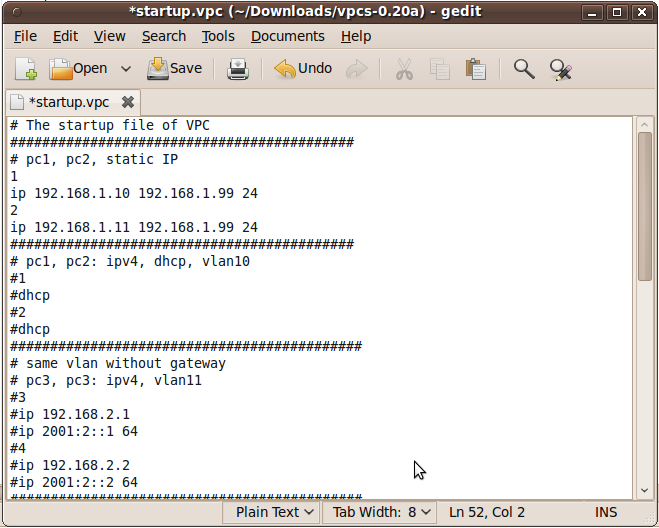
4.Then we'll open and configure startup.vpc in gedit
gedit startup.vpc

5.Now configure startup.vpc according to your requirement. For example I'll add just two hosts for this tutorial.
Host 1 (VPCS1) with Ip 192.168.1.10/24 and 192.168.1.99 as its gateway.
Host 2 (VPCS2) with Ip 192.168.1.11/24 and 192.168.1.99 as its gateway.
** add # to the rest of the lines.
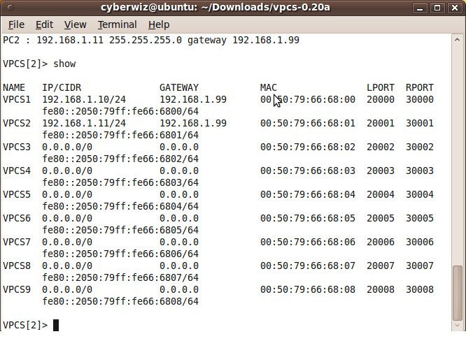
6.Now lets start VPCS by issuing the following command within the terminal.
./vpcs32.linux
7.Use show command to see all the configured ip addresses.
Fire up GNS3 (run gns3 as a root).
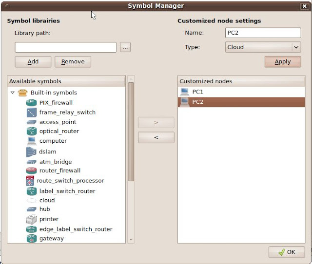
9.This is a optional step where I'll be adding symbols to PC hosts.

10.Add computer symbol from 'available symbol' to 'customized nodes'
on name = anyname ie, PC1
on type = Cloud
click ok
Do the same for PC2
11.Drag and Drop PC1 and PC2 into the GNS3 Workboard.
Double click on PC1
click on 'C1'
go to tab 'NIO UDP'
hold....
go back to Step 7
Check the LPORT and RPORT
12.On Local port add rport value
on Remote port add lport value
on Remote host add 127.0.0.1
click add
Do the same for PC2 (again check the respective ports)

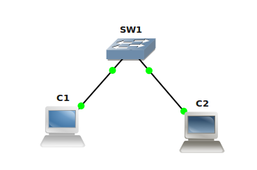
14. Maximize vpcs window and lets ping to each host to check the connectivity between them.
To navigate from 1 pc to another, simply type the number

As you see, a successful connectivity has been established between the two hosts.
Happy Learning :)
Configure Terminal Server
1. Configure an IP address on the ethernet interface
cisco(config)# int fa0/0
cisco(config-if)# ip add 192.168.1.50 255.255.255.0
cisco(config-if)# no shut
2. Create a loopback interface
cisco(config)# int lo0
cisco(config-if)# ip add 1.1.1.1 255.0.0.0
3. Configure the line based on the “show line” output.
* If enabled, the port will be accessible through the network on TCP port 20xx where xx is the TTY of the port on the router
cisco(config)# line 1 16
cisco(config-line)# no exec //unwanted signals from the attached device do not launch.
cisco(config-line)# exec-timeout 0 0 //disable the line timeout period
cisco(config-line)# logging synchronous
cisco(config-line)# transport input all
4. Configure default route
cisco(config)# ip route 0.0.0.0 0.0.0.0 192.168.1.1
cisco(config)# ip default-gateway 192.168.1.1
// ip default-gateway is configured as well in case routing is not enabled. E.g. the terminal server is in ROMMON mode as a result of a bad reboot after power outage.
5. Enable telnet line
cisco(config)# line vty 0 4
cisco(config-line)# password cisco
cisco(config-line)# login
6. Configure host and line mapping
*e.g. Router A is connected to line 1
cisco(config)# ip host RouterA 2001 1.1.1.1
Enable SSH in Switch and Router
Assuming the IP address, enable password and default route are in place, the additional steps needed are as follows:
1. Configure a domain name
cisco(config)# ip domain-name cisco.com
2. Configure the RSA key generation for encryption
cisco(config)# crypto key generate rsa
* it may prompt user for the key length generated in the range of 360 to 2048. Default is 512-bit.
3. Configure authentication method
a) Using local database
cisco(config)# username cisco password cisco
OR
b) Using Radius server
cisco(config)# aaa new-model
cisco(config)# aaa authentication login Radius_Server group radius
cisco(config)# radius-server host 192.168.1.155
4. Configure the terminal line
cisco(config)# line vty 0 4
cisco(config-line)# login local // using local database
OR
cisco(config-line)# login authentication Radius_Server //using radius server
cisco(config-line)# transport input ssh
Subnet Chart:Internet Protocol (IPv4)
This is an Internet Protocol (IPv4) Subnet Chart. You can use this to quickly look up how you might need to subnet your network. At the bottom there is a quick how-to on calculating subnets.
For more information on subnetting, see RFC 1817 and RFC 1812.
Class address ranges:
Class A = 1.0.0.0 to 126.0.0.0
Class B = 128.0.0.0 to 191.255.0.0
Class C = 192.0.1.0 to 223.255.255.0
Reserved address ranges for private (non-routed) use (see RFC 1918):
10.0.0.0 -> 10.255.255.255
172.16.0.0 -> 172.31.255.255
192.168.0.0 -> 192.168.255.255
Other reserved addresses:
127.0.0.0 is reserved for loopback and IPC on the local host
224.0.0.0 -> 239.255.255.255 is reserved for multicast addresses
Chart notes:
Number of Subnets - "( )" Refers to the number of effective subnets, since the use of subnet numbers of all 0s or all 1s is highly frowned upon and RFC non-compliant.
Number of Hosts - Refers to the number of effective hosts, excluding the network and broadcast address.
Class A
| Network Bits | Subnet Mask | Number of Subnets | Number of Hosts |
| /8 | 255.0.0.0 | 0 | 16777214 |
| /9 | 255.128.0.0 | 2 (0) | 8388606 |
| /10 | 255.192.0.0 | 4 (2) | 4194302 |
| /11 | 255.224.0.0 | 8 (6) | 2097150 |
| /12 | 255.240.0.0 | 16 (14) | 1048574 |
| /13 | 255.248.0.0 | 32 (30) | 524286 |
| /14 | 255.252.0.0 | 64 (62) | 262142 |
| /15 | 255.254.0.0 | 128 (126) | 131070 |
| /16 | 255.255.0.0 | 256 (254) | 65534 |
| /17 | 255.255.128.0 | 512 (510) | 32766 |
| /18 | 255.255.192.0 | 1024 (1022) | 16382 |
| /19 | 255.255.224.0 | 2048 (2046) | 8190 |
| /20 | 255.255.240.0 | 4096 (4094) | 4094 |
| /21 | 255.255.248.0 | 8192 (8190) | 2046 |
| /22 | 255.255.252.0 | 16384 (16382) | 1022 |
| /23 | 255.255.254.0 | 32768 (32766) | 510 |
| /24 | 255.255.255.0 | 65536 (65534) | 254 |
| /25 | 255.255.255.128 | 131072 (131070) | 126 |
| /26 | 255.255.255.192 | 262144 (262142) | 62 |
| /27 | 255.255.255.224 | 524288 (524286) | 30 |
| /28 | 255.255.255.240 | 1048576 (1048574) | 14 |
| /29 | 255.255.255.248 | 2097152 (2097150) | 6 |
| /30 | 255.255.255.252 | 4194304 (4194302) | 2 |
Class B
Network Bits | Subnet Mask | Number of Subnets | Number of Hosts |
| /16 | 255.255.0.0 | 0 | 65534 |
| /17 | 255.255.128.0 | 2 (0) | 32766 |
| /18 | 255.255.192.0 | 4 (2) | 16382 |
| /19 | 255.255.224.0 | 8 (6) | 8190 |
| /20 | 255.255.240.0 | 16 (14) | 4094 |
| /21 | 255.255.248.0 | 32 (30) | 2046 |
| /22 | 255.255.252.0 | 64 (62) | 1022 |
| /23 | 255.255.254.0 | 128 (126) | 510 |
| /24 | 255.255.255.0 | 256 (254) | 254 |
| /25 | 255.255.255.128 | 512 (510) | 126 |
| /26 | 255.255.255.192 | 1024 (1022) | 62 |
| /27 | 255.255.255.224 | 2048 (2046) | 30 |
| /28 | 255.255.255.240 | 4096 (4094) | 14 |
| /29 | 255.255.255.248 | 8192 (8190) | 6 |
| /30 | 255.255.255.252 | 16384 (16382) | 2 |
Class C
Network Bits | Subnet Mask | Number of Subnets | Number of Hosts |
| /24 | 255.255.255.0 | 0 | 254 |
| /25 | 255.255.255.128 | 2 (0) | 126 |
| /26 | 255.255.255.192 | 4 (2) | 62 |
| /27 | 255.255.255.224 | 8 (6) | 30 |
| /28 | 255.255.255.240 | 16 (14) | 14 |
| /29 | 255.255.255.248 | 32 (30) | 6 |
| /30 | 255.255.255.252 | 64 (62) | 2 |
Supernetting (CIDR) Chart
CIDR - Classless Inter-Domain Routing.
Note: The Number of Class C networks must be contiguous.
For example, 192.169.1.0/22 represents the following block of addresses:
192.169.1.0, 192.169.2.0, 192.169.3.0 and 192.169.4.0.
Class C
| CIDR Block | Supernet Mask | Number of Class C Addresses | Number of Hosts |
| /14 | 255.252.0.0 | 1024 | 262144 |
| /15 | 255.254.0.0 | 512 | 131072 |
| /16 | 255.255.0.0 | 256 | 65536 |
| /17 | 255.255.128.0 | 128 | 32768 |
| /18 | 255.255.192.0 | 64 | 16384 |
| /19 | 255.255.224.0 | 32 | 8192 |
| /20 | 255.255.240.0 | 16 | 4096 |
| /21 | 255.255.248.0 | 8 | 2048 |
| /22 | 255.255.252.0 | 4 | 1024 |
| /23 | 255.255.254.0 | 2 | 512 |
The first thing you must know is that the common number system used world wide is the decimal system (otherwise known as base 10). What makes the decimal system a base 10 system is that it is based on grouping numbers by 10's. It is believed that the system evolved because we have ten fingers and ten toes which over the years we have used for counting. I use mine all the time (grin). We name the ten digits: zero, one, two, three, four, five, six, seven, eight and nine.
The decimal system has a 1's place, a 10's place, a 100's place, a 1000's place and so on. We say the number places are grouped by 10's because multiplying each number place by 10 gives you the next number place. So: 1x10=10 (the 10's place), 10x10=100 (the 100's place), 100x10=1000 (the 1000's place) etc.
Let's look at the decimal number 103 by place.
103 <- read from right to left
We have a 3 in the 1's place
We have a 0in the 10's place
We have a 1 in the 100's place
Thus: 100+0+3=103
By now you probably feel like you have attended Kindergarten for the second time in your life? Sorry about that but it is very important that you understand the concept of what a number system is, and what it is based on before we look at binary.
[Understanding binary - base 2]
Binary is a base 2 system, and thus groups numbers by 2's and not by 10's like the decimal system. We name the two digits: zero and one. The binary system has a 1's place, a 2's place, a 4's place, an 8's place, a 16's place and so on. We say the number places are grouped by 2's because multiplying each number place by 2 gives you the next number place. So: 1x2=2 (the 2's place), 2x2=4 (the 4's place), 4x2=8 (the 8's place), 8x2=16 (the 16's place) etc.
Let's look at the decimal number Let's look at the decimal number 103 in binary format:
01100111 <- read from right to left
We have a 1 in the 1's place
We have a 1 in the 2's place
We have a 1 in the 4's place
We have a 0 in the 8's place
We have a 0 in the 16's place
We have a 1 in the 32's place
We have a 1 in the 64's place
We have a 0 in the 128's place
Thus: 0+64+32+0+0+4+2+1=103
Okay, Let's test your skills. Here is a list of binary numbers, try converting them to decimal and check your answers at the end of this post.
10000000
11000000
11100000
01000000
10000011
10010001
11111111
If you were able to convert these numbers to decimal then congratulations! You're ready to move on to the next section.
[Understanding a subnet mask]
Now that you understand what binary is, let's have a look at our two subnet masks from the beginning of my post:
192.168.1.0 / 255.255.255.0
192.168.1.0/24
The concept of a subnet mask is simple. You have a network and you have hosts on the network (anything with an IP address is a host). The subnet mask determines what portion of the TCP/IP address represents your network and what portion can be used for your hosts. Because I am a simple person, I think of it like this; The network number represents the street I live on, and the host portion is used for the numbers on all the houses on my street.
A subnet mask of 255.255.255.0 means that the first three octets of the address will be used for the network, and thus our network number is 192.168.1. This means we can have 254 computers on this network, because the fourth octet is not being used by the network portion of the address. We know this because of the 0 in the subnet mask (255.255.255.0).
We call each of the number sections an octet because we think of them in binary, and there are eight possible bits in each section. Eight bits is an octet. 11111111 in binary is 255 in decimal (did you do the conversions?). So our decimal subnet mask 255.255.255.0 displayed in binary is going to be:
11111111.11111111.11111111.00000000
If you count all the ones, you will find that there are 24 of them. Now look at the subnet mask examples again.
192.168.1.0/255.255.255.0
192.168.1.0/24
Do you see why both subnet masks are the same? The number 24 is the number of bits used in the network portion of the address, and is short-hand for writing the address/subnet mask combination. It becomes important to understand this when you start dividing your network into multiple sub networks.
[Understanding Subnetting]
Before reading this section, you should have a good understanding of what a subnet mask is and how binary bits represent the subnet mask.
Simply put, subnetting is dividing your network into multiple sub networks. To go back to my silly example about houses and streets, subnetting gives you multiple streets in your neighborhood.
There are two methods for dividing your network into multiple sub networks; One is to simply change your network numbers keeping the same subnet mask. The other is to subnet your network into smaller sub networks.
Keeping the same mask:
Your network could be divided into two or more networks by changing the network portion of the address such as 192.168.1 and 192.168.2 and keeping the same subnet mask.
Example:
192.168.1.0/255.255.255.0
192.168.2.0/255.255.255.0
Doing this would give you two separate networks with 254 hosts per network. This is a very common method of dealing with multiple networks. However, back in the good old days you had to pay for every IP address you used, and if you had 25 computers on your network you probably would not want to pay for 254 addresses! The answer to the problem is...subnetting.
Subnetting a network:
Subnetting is when you use bits from the host portion of your address as part of your network number. This let's you subdivide your network at the cost of host addresses, which is great if you're paying for every host IP address. It will save you money because you pay for fewer TCP/IP addresses. Confused? Here is where understanding binary is important.
Lets look at a new subnet mask:
255.255.255.224
As you can see in the fourth octet, some of the host portion of this subnet mask is now being used for part of the network address. Which means we are now using some of the binary bits in the fourth octet for our network numbers, and that gives us fewer hosts than our old mask (which gave us 254), but gives us more networks (which is why we call it subnetting).
How can we tell how many networks and hosts per network this new subnet mask will give us? Well... we shall have to use some of our newly acquired binary skills.
The first task is to find out how many bits in the fourth octet are being used? The decimal number is 224, what is the decimal number 224 as represented in binary?
The decimal number 224 in binary is:
11100000
We have a 0 in the 1's place
We have a 0 in the 2's place
We have a 0 in the 4's place
We have a 0 in the 8's place
We have a 0 in the 16's place
We have a 1 in the 32's place
We have a 1 in the 64's place
We have a 1 in the 128's place
Thus: 128+64+32+0+0+0+0+0=224
So our complete subnet mask in binary is:
1111111.11111111.11111111.11100000
We now know that three bits from the fourth octet are used. How can we tell how many sub networks we're going to have? This requires some math- sorry. The formula is: 2n-2, where n is the number of bits being used from the host portion of our subnet mask.
Note: We subtract 2 from the total because you do not count all 0's or all 1's.
The formula for three bits is:
23-2=6
In simpler terms:
(2x2x2)-2=6
So our network is sub divided into 6 networks. Next, we want to know what the network numbers are, and how many hosts we can have on each of the 6 networks?
What is the first subnet? Let's have a look at the bits in our fourth octet again. The bit that gives us the answer is the (1) closest to the first zero, and in this case it is the 3rd bit from the left.
11100000
The 3rd bit will start our first network, and the 3rd bit is in the 32's place (remember binary). Start adding the value 32 to itself six times to get the six network numbers.
Note: A quicker way to find our starting network number is to subtract our mask from 256.
256-224=32
Here are our network numbers:
32
64
96
128
160
192
A better way to display this is:
192.168.1.32
192.168.1.64
192.168.1.96
192.168.1.128
192.168.1.160
192.168.1.192
The host addresses will fall between the network numbers, so we will have 30 hosts per network. You're probably wondering why it's not 31? The answer is that the last address of each subnet is used as the broadcast address for that subnet.
Example:
Subnet:192.168.1.32 / 255.255.255.224
Address Range: 192.168.1.33 through 192.168.1.62 (30 hosts)
Subnet Broadcast Address:192.168.1.63
Quiz:
Let's test your skills- write the address range and broadcast address for the following subnet. You will find the answer at the end of this post.
Subnet: 192.168.1.128 / 255.255.255.224
Address Range?
Subnet Broadcast Address?
If we we're paying for our TCP/IP addresses, we would only pay for one network and host combination, thus paying for 30 hosts and not 254. It could mean some real savings, it also frees up the remaining addresses for other organizations to use.
Let's look at another subnet mask:
255.255.255.240
How many bits are used from the host portion? To find this out, we need to know how the decimal number 240 is represented in binary.
The answer is:
11110000
So four bits are taken from the host portion of our mask. We do the same math as before:
24-2=14
In simpler terms:
(2x2x2x2)-2=14
We will have 14 sub networks, and what will the network numbers be? Look at the fourth bit, it's in the 16's place:
11110000
Note: A quicker way to find our starting network number is to subtract the value of our mask from 256. So: 256-240=16
Start adding 16 to itself- fourteen times to get all 14 network numbers:
16
32
48
64
80
96
112
128
144
160
176
192
208
224
A better way to display our subnets is:
192.168.1.16
192.168.1.32
192.168.1.48
192.168.1.64
192.168.1.80
192.168.1.96
192.168.1.112
192.168.1.128
192.168.1.144
192.168.1.160
192.168.1.176
192.168.1.192
192.168.1.208
192.168.1.224
The host addresses fall between the network numbers. So we will have 14 host addresses on each of our 14 sub networks (remember: the last or 15th address is the broadcast address for that subnet).
If you had a small company with 10 hosts and needed to have a static IP address for all of your hosts, you would be assigned a network/subnet mask and a valid IP address range.
Here is an example of what that might look like:
Network: 205.112.10.16/.255.255.255.240
Address Range: 205.112.10.17 through 205.112.10.30
Subnet Broadcast Address: 205.112.10.31
[Answers to Binary Conversions]
10000000 = 128
11000000 = 192
11100000 = 224
01000000 = 64
10000011 = 131
10010001 = 145
11111111 = 255
[Answer to Subnet Question]
Subnet:192.168.1.128 / 255.255.255.224
Address Range: 192.168.1.129 through 192.168.1.158
Subnet Broadcast Address: 192.168.1.159
Add GUI QEMU Host in GNS3
Today I’ll show you how to add graphical host in GNS3 using Qemu. We’ll be using tinycore which is based on Linux 2.6 kernel, Busybox, Tiny X, and Fltk. Tiny Core includes ssh, iptables, iproute, tcpdump and IPv6 support. It is quite well integrated and doesn't require much tuning. This is a graphical version of Microcore linux image, we used in previous tutorial Add Qemu host in GNS3 .
Setup image for Qemu host

- Identifier: tiny_core
- image: local path to linux-tinycore-2.11.5.img
- Memory: 64 MB
- NIC: e1000
- Qemu options: -no-acpi
Press Save and just added image will appear into Qemu Host images list.
Drag Host >> Select Name >> Right Click >> Start

Happy Learning
Putty Connection Manager
If you work with Cisco or Linux you are probably used to working with a terminal window. When you have several terminal windows on your desktop this might become a bit annoying when they are all scattered around the screen. Putty connection manager solves this problem! Best Part is Putty Manager can be used with GNS3.

By using Putty Connection Manager you can use tabs to keep your terminal windows under control. You can split windows horizontally or vertical and customize it exactly the way you like...very nice!
You can download putty connection manager from this website:
http://puttycm.free.fr/cms/
Cisco Routing & Switching Certifications
Cisco offers different "tracks" when it comes to certification:
- Routing & Switching
- Design
- Network Security
- Service Provider
- Service Provider Operations
- Storage Networking
- Voice
- Wireless
- CCNA (Cisco Certified Network Associate)
- CCNP (Cisco Certified Network Professional)
- CCIE (Cisco Certified Internetwork Expert)
On the Cisco website you will always see this pyramid when they are talking about certifications:

At the bottom you see the "entry" level, I'm skipping that one and jumping right to the "Associate" level (CCNA) because that's where most people are starting. As you can see the bottom is very width, and if you go to the professional (CCNP) and expert (CCIE) level it's narrow.This image is chosen for a reason.
CCNA
If you start with studying Cisco, you'll start with the Associate level (CCNA). There are a lot of topics and technologies that you might have never heard about, so there's a lot of studying for you to do...I believe this makes it a hard exam for newcomers. If you want to self-study for CCNA I recommend you to get this book:CCNA: Cisco Certified Network Associate Study Guide: Exam 640-802

It covers all the topics for the exam, if you read this book a couple of times and do all the exercises...you'll have a very good basic understanding of networking. It shows you the basics of networking, switching, routing, ip, etc.
You can get the CCNA certification by doing 2 separate or a combined exam. If you do the combined exam you need to get a higher score and I only suggest doing this when you feel really confident about your networking knowledge or already have experience.
To beat Cisco exams you need to get hands-on experience. You can achieve this by buying old equipment (from eBay) and practice. This is what you will need at least:
2x Cisco 2950 Catalyst Switch. (any version will do)
2x Cisco 2610 Router with at least 1x Fast Ethernet and 1x Serial Connection.
1x Serial Console Cable (those are the famous blue Cisco cables for console connections)
1x Serial Cable
1x Serial 2 USB (in case you don't have a serial port on your PC or laptop).
If you are planning to continue studying Cisco I would suggest to buy Cisco 2550 Catalyst Switches instead of the 2950's, they are more useful for your CCNP.
It's possible to skip the routers because you can run Cisco IOS (Cisco's Operating System) on your PC or laptop by using GNS3. You can find a brief tutorial on GNS3 here.
Cisco 2610 Router

Cisco Catalyst 2950 Switch

Cisco Serial Console Cable:

Cisco Serial Cable:

CCNP
This equipment and the study guide should help you to pass your CCNA, Now if you want to continue studying your CCNP you will find that this is much easier (that's my opinion) then when you studied for your CCNA. When you started with the CCNA you had to study complete new material that you perhaps never heard or read about before, now you have a basic level of networking knowledge that you will further develop.To achieve your CCNP certification you need to pass 3 exams:
- Route (Routing)
- Switch (Switching)
- Tshoot (Troubleshooting)
Routing TCP/IP Volume 1:
This book isn't special for the CCNP but covers all the interior routing protocols and is written very well, a must read for every networking professional.

Routing TCP/IP Volume 2:
Sometimes more is better and that is definitely true for Routing TCP/IP. This book is more about BGP (Border Gateway Protocol), NAT and some IPv6.

The other books you should read are the Cisco Press books that cover the exam goals:
CCNP Route:
This is the official Cisco Press book, covers everything you need to know for the "Route" exam.

CCNP Switch:
Also the official Cisco Press book about the Switch exam. Teaches you everything about switching you need to know to pass the exam.

CCNP Tshoot:
Troubleshooting networks is fun, this book will show you everything you need to know.

Besides reading books you need to increase your hands-on experience...do more labs, build networks and so on. You can do a lot of labs with routers by using the dynamips/gns3 software. Checkout my tutorials on GNS3 here.
The new Cisco exams are very "practical". This means you will get a lot of questions you cannot answer if you don't have the hands-on experience. You need to build networks...do labs, try stuff out. Just reading the books is not going to be enough!
CCIE
Now the CCIE is a completely different beast. Honestly you can't compare this to CCNA or CCNP level. To pass the CCIE you need to do a written exam and pass the lab.How to run Linux Router Vyatta in GNS3
What is the Vyatta ?
Vyatta is bringing innovation and affordability to the networking industry by delivering advanced routing and security in a software-based network OS that scales from the branch office to the service provider edge. Vyatta has decoupled networking software from proprietary hardware allowing users to leverage the price and performance advantages of standard x86-based hardware and components as well as Citrix XenServer and VMWare virtual or cloud environments.http://www.vyatta.com/
In this tutorial brezular shows us how to install Vyatta 6.1 Core LiveCD on Qemu image and run it from GNS3.
1. Download Vyatta Core 6.1 LiveCD iso (You need to fill short questionnaire for Vyatta download)
Vyatta download http://www.vyatta.com/downloads/index.php
2. Create Qemu qcow2 image
/usr/local/bin/qemu-img create -f qcow2 ./vyatta6.1vc.img 1G
3. Boot Qemu image with Vyatta 6.1 LiveCD
/usr/local/bin/qemu -boot d -hda ./vyatta6.1vc.img -cdrom ./vyatta-livecd_VC6.1-2010.08.20_i386.iso -m 512
login/password: vyatta/vyatta
4. Install Live CD
To install Live CD to Qemu image enter this command (as user vyatta)
install-system
The tutorial is opened and it walk you through installation process:
Would you like to continue? (Yes/No) [YES]: Enter
Partition (Auto/Union/Parted/Skip) [Auto]: Enter
Install the image on? [sda]: Enter
This will destroy all data on /dev/sda.
Continue? (Yes/No) [No]: Yes
How big of root partition should I create? (1000MB – 1074MB) [1074]MB: Enter
I found the following configuration files
/opt/vyatta/etc/config/config.boot
Which one should I copy to sda? [/opt/vyatta/etc/config/config.boot] Enter
Enter password for administrator account
Enter vyatta password: your_password
Retype vyatta password: your_password
Which drive should GRUB modify the boot partition on? [sda]: Enter
Done!
Now you successfully install Vyatta.
5. Adapt Vyatta NIC behavior to GNS3 Qemuwrapper
GNS3 qemuwrapper always changes MAC address of presented NIC during the boot of Qemu instance. Vyatta is programmed to save MAC address of existing ethernet interfaces. If MAC address of particular NIC is changed (by GNS3 qemuwrapper) Vyatta preserves the interface with old MAC and create new interface with new MAC.
Each time Qemu instace is restarted the number of interfaces doubled.
These are my steps how to solve it (it must be a better solution but I didn’t find any with Google search):
a) Enable root account on Vyatta 6.1
thank to Tim Peerlings blog http://www.timpeerlings.nl/enable-root-account-on-vyatta-6-1/
vyatta$ configure
vyatta#set system login user root authentication plaintext-password test
vayata# commit
vyatta# save
exit
Now you should switch to user root:
su
Password: test
b) Remove vyatta_net_name script (root account needed)
cd /lib/udev/
mv ./vyatta_net_name ./vyatta_net_name_backup
rm ./vyatta_net_name
6. Setup serial console login
thanks to Petr’s blog http://linux.xvx.cz/2009/08/debian-with-grub2-and-serial-connection/
This configuration redirects output to serial ttyS0 and allows you to use Console in GNS3.
Login as root with su command and modify grub configuration file:
vim /etc/default/grub
Change the lines in configuration file according to these lines
# This file is sourced by update-grub, and its variables are propagated
# to its children in /etc/grub.d/
GRUB_DEFAULT=0
GRUB_TIMEOUT=0
GRUB_DISTRIBUTOR=`lsb_release -i -s 2> /dev/null || echo Debian`
GRUB_CMDLINE_LINUX_DEFAULT=”console=tty0 console=ttyS0,9600n8″
# Uncomment to disable graphical terminal (grub-pc only)
GRUB_TERMINAL=serial
GRUB_SERIAL_COMMAND=”serial –speed=9600 –unit=0 –word=8 –parity=no –stop=1″
# Uncomment if you don’t want GRUB to pass “root=UUID=xxx” parameter to LinuxNow update grub with command:
#GRUB_DISABLE_LINUX_UUID=true
update-grub
7. Setup GNS3 for Vyatta qemu image
- Start GNS3
- Edit-> Preferences-> Qemu-> Qemu Host
Set your settings according to picture:

Check Kvm option only if your processor supports hardware virtualization. Check Kqemu option only if it is installed and running. If you are not sure with these options let them unchecked otherwise Qemu will be not started.
You need also set Qemu general settings like path to qemu, qemu-img and qemuwrapper.
- Edit-> Preferences-> Qemu-> General Settings
Check the picture for details:

Login to Vyatta:
login/password: vyatta/your_password
8. Conclusion
Brezular has made a video to prove functionality of Yvatta Qemu image. In this video three Vyatta Qemu instances run RIP routing protocol.
Video: RIP configuration on Vyatta box:
http://rapidshare.com/files/419301470/vyatta_on_qemu_gns3.rar.html
You can download Vyatta 6.1 Qemu image from here:
http://rapidshare.com/files/420013925/vyatta6.1vc.part1.rar
http://rapidshare.com/files/420013926/vyatta6.1vc.part2.rar
login/pass: vyatta/skuska
root account: root/skuska (Don’t use root account for router configuration)
If you use Linux and there is already non-patched Qemu installed in your distro don’t forget to patch, compile and install Qemu for udp tunnels and multicast. The great How to is here:
http://blog.gns3.net/2009/10/olive-juniper/2/
Special Thanks to Brezular for this great tutorial.
All About GNS3
You can find some user based support on the Freenode network of IRC.
Server: irc.freenode.com
Channels:
#gns3: Focuses on support for the GNS3 product (bugs, recommendations, complaints)
#gns3-labs: Aimed to help with labs and trade topologies.. Not an official GNS3 support channel.
Dynamips Tutorial: Dynagen is a front-end for use with the Dynamips Cisco router emulator
7200emu.hacki.at: A forum for everything GNS3, Dynamips, Dynagen and overall help.
BlindHog.net: Great website with videos, configs and files on setting up working labs with some troubleshooting and testing exercises.
BrainBump: This website is dedicated for helping those who are working towards achieving their CCIE.Personally, The author is working towards CCIE voice and this blog will help those who are pursuing Voice/Security/RS CCIE’s.
- Need help installing GNS3 on Windows XP?
- A new tutorial for GNS3 0.5 is available here (highly recommended for beginners). OUTDATED
- Need help installing GNS3 on a Linux platform?
-
Video tutorials
Beginners
- Internet LAB Tutorial Part 2
- Installation Tutorial for Linux
- How to build an Internet Lab
- GNS3 Graphical router emulation software
- Switching lab Part 2 (router on a stick)
-
Switching
- How to build a switching lab Part 1
- How to install and enable ASDM (PIX firewall) using GNS3
- How to configure IOS IPS (Intrusion Prevention System) using SDM in GNS3
- How to use Pemu as your personal firewall
- How to communicate with Pemu
- Pemu PIX emulator with GNS3
-
Voice
- How to build a voice lab with GNS3 and VMWare
- How to use a third party SIP phone with Cisco routers using GNS3
- How to setup Call Manager Express (CME) router using GNS3
- How to configure Cisco Unified Call Manager Express GUI using GNS3
- How to configure Cisco Unified Call Manager Express (CUCME) router for XML Services
- How to register third party SIP phone to Cisco Unified Call Manager Express (CUCME)
- How to setup CME SIP trunk to VoIP SIP Service Provider Part 1
- How to save labs with router configs
- How to build a frame-relay lab
- How to integrate a Microsoft Loopback interface with GNS3
- How to use Putty for console access
- How to use Putty Connection Manager for console access
-
Misc
- How to setup and install Cisco Security Device Manager (SDM) on router using GNS3
- How to setup and configure Cisco Configuration Professional (CCP)
- How to lockdown Cisco Router’s Configuration Access
- How to configure and setup IPv6 connectivity between Windows XP and Cisco Router
- How to run multi-pc topology using distributed hypervisors in GNS3
Cisco Packet Tracer Video Tutorials

English | MP4 | 1920x1080 | AVC - 1108 Kbps | AAC - 126 Kbps | 916.16 MB
Genre: Video Training
Cisco Networking Academy is a comprehensive e-learning initiative that enables students to develop valuable information and communication technology skills for increased access to opportunities in the global economy. To learn more about the program, how to get involved, career resources for students, how we are addressing the digital divide, and more. Packet Tracer is an application produced by Cisco Systems to provide a virtual simulation of real life equipment and situations.
Contains
Cisco Systems Packet Tracer
Packet Tracer OSPF
Packet Tracer Subinterfaces
Packet Tracer Video
Switch VLAN
WAN connection ADSL
CCNA 3 Ch 1 Lab Intro using Packet Tracer 5.0.mp4
Cisco Systems Packet Tracer
configuration frame relay.mp4
EIGRP,FRAME RELAY, HTTP AND DNS Packet Tracer.mp4
Frame-Relay Packet Tracer 5.2 (Cisco) Tagalog Tutorial.mp4
How to configure OSPF in Packet Tracer..mp4
How to configure RIPv2 in Packet Tracer..mp4
Multiuser Connection Packet Tracer 5.1.mp4
OSPF Authentication Lab using Packet Tracer 5.mp4
Packet Tracer - DHCP Server with IP Helper.mp4
Packet Tracer - DHCP Setup.mp4
Packet Tracer OSPF
Packet Tracer Sub interfaces
Packet Tracer Video
Packet Tracer VLANS
Static Routing using Packet Tracer 5.0.mp4
Switch Router Vlan Packet Tracer.mp4
Switch VLAN
Testing Security Policies with Packet Tracer.mp4
Tutorial Packet Tracer 5.1 Nube Fame Relay.mp4
using packet tracer Connecting to a web server using IP.avi.mp4
VTP Trunk VLAN.mp4
WAN connection ADSL
Wifi con Packet Tracer.mp4

http://hotfile.com/dl/68710663/8efd2b5/PacketTracerTutorial.part01.rar_gigatraining.net.html
http://hotfile.com/dl/68710657/a691c62/PacketTracerTutorial.part02.rar_gigatraining.net.html
http://hotfile.com/dl/68710660/26ace7c/PacketTracerTutorial.part03.rar_gigatraining.net.html
http://hotfile.com/dl/68710655/f104c16/PacketTracerTutorial.part04.rar_gigatraining.net.html
http://hotfile.com/dl/68710658/73c885f/PacketTracerTutorial.part05.rar_gigatraining.net.html
http://hotfile.com/dl/68710661/bb0f5a3/PacketTracerTutorial.part06.rar_gigatraining.net.html
http://hotfile.com/dl/68710656/b9b8886/PacketTracerTutorial.part07.rar_gigatraining.net.html
http://hotfile.com/dl/68710659/9174699/PacketTracerTutorial.part08.rar_gigatraining.net.html
http://hotfile.com/dl/68710662/a02ca42/PacketTracerTutorial.part09.rar_gigatraining.net.html
http://hotfile.com/dl/68710664/7f953f1/PacketTracerTutorial.part10.rar_gigatraining.net.html

Password default: gigatraining.net


